
Use case · CAD Customization
Automated Utility Structure Design & Fabrication Integration
PLS-Pole signs off the structure, and then the real clock starts: modelling it in Inventor, detailing the drawings, and preparing fabrication data by hand. We built the add-in that does all three, straight through to Tekla PowerFab.
The challenge
The analysis took hours. The documentation took the rest of the week.
For a manufacturer of tubular steel transmission poles and utility structures, the engineering was the fast part. Once PLS-Pole confirmed a structure, days of manual production followed: rebuilding the geometry in Inventor, detailing fabrication drawings sheet by sheet, retyping BOMs for manufacturing. Output varied with whoever produced it. Rework was routine. And every new project added volume the team could only absorb by adding people.
What made it hard
What the manual workflow was costing
The solution
One add-in, from analysis output to fabrication data
FDES built a custom Autodesk Inventor add-in that picks up exactly where PLS-Pole stops. Structured inputs go in; complete models, drawings, BOMs, and fabrication-ready data come out the other end.
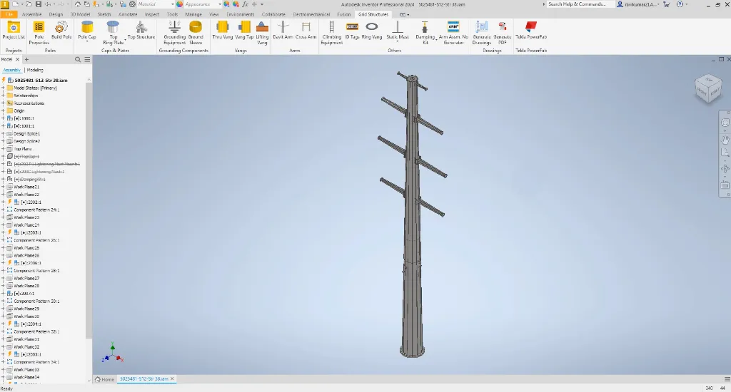
- Rules turn structured inputs into structures: no freehand modelling.
- Parts, sub-assemblies, and full assemblies generate themselves.
- Drawings and PDFs come off standardized templates in a single click.
- Part numbers assign and hardware places automatically: no naming debates.
- BOMs arrive manufacturing-ready, not draft-ready.
- Fabrication data exports structured to match Tekla PowerFab requirements.
Delivered scope
Everything between analysis and the shop floor
End-to-end data flow
Integrations
Design data moves through the chain without being retyped anywhere along the way.
Autodesk Inventor
Where the models, drawings, and BOMs are generated.
Tekla PowerFab
Receives structured fabrication packages directly.
Excel/CSV
Feeds batch inputs into the automation.
Technologies used
Measured outcome
What changed in production
Per structure type
The design-to-fabrication cycle dropped from 2 weeks to 2-3 days per structure type.
Fabrication errors from drawings
Zero fabrication errors traced to drawing inconsistencies; rule-based validation stops mismatches before release.
Engineering time returned
60% of the time once spent on repetitive documentation and BOM generation now goes to engineering.
To fabrication
Inventor data lands in cutting and welding systems directly; nobody retypes it in between.
The difference
One structure, both ways
Related
More systems like this one
Next step
Still Carrying Structures From Analysis to Fabrication by Hand?
Walk us through your workflow, from structural analysis to the shop floor. We'll tell you which stretch of it automates cleanly, where the risk actually sits, and what a production-grade build would look like.
- Design-to-fabrication cycle: 2 weeks → 2–3 days
- Zero fabrication errors from drawing inconsistencies
- 60% of engineering time freed from documentation
- Direct Inventor-to-Tekla PowerFab data flow