The Manual Workflow: Where Engineering Hours Go
To understand what automation replaces, you need to see the manual process clearly. Most transmission pole manufacturers follow a workflow that looks roughly like this:
Step 1: Structural Analysis in PLS-Pole
Your structural engineers run PLS-Pole to analyze loading conditions, determine pole geometry, select materials, and validate structural adequacy. This step produces the design parameters: pole dimensions, wall thicknesses, taper ratios, base plate sizes, arm configurations, vang details, and hardware requirements.
PLS-Pole does its job well. The problem starts after the analysis is complete.
Step 2: Manual Parameter Transfer
An engineer or drafter takes the PLS-Pole output and begins manually entering parameters into Autodesk Inventor. Pole diameter at the top and bottom. Wall thickness per section. Taper angles. Base plate dimensions. Arm lengths and orientations. Vang specifications. Hardware selections.
This transfer step is tedious and error-prone. A misread dimension, a transposed number, or a missed parameter creates errors that compound through every downstream deliverable.
Step 3: 3D Model Construction
The drafter manually builds the 3D model in Inventor. For a typical tubular steel transmission pole, this includes:
- Pole shaft: Tapered sections with correct diameters, wall thicknesses, and lengths
- Base plate: Correct dimensions, bolt patterns, and weld preparations
- End plates and connections: Top plate, splice details, connection hardware
- Vangs: Type, orientation, dimensions, material, and attachment details
- Arms: Cross-arm or davit arm geometry, connection details, bolt patterns
- Hardware: Bolts, nuts, washers, insulators, climbing hardware
Each component must be modelled individually and assembled correctly. A typical pole with arms, vangs, and full hardware can take 8-12 hours of modelling time alone.
Step 4: 2D Drawing Generation
From the 3D model, the drafter creates fabrication-ready 2D drawings. This involves:
- Placing standard views (front, side, top, section views, detail views)
- Adding all dimensions per your company's drawing standards
- Placing weld symbols, surface finish callouts, and general notes
- Populating the title block with project information, revision data, and approval fields
- Creating separate detail sheets for complex components
- Adding cross-references between assembly and detail drawings
This step alone can consume 4-8 hours per pole design, depending on complexity and drawing standards.
Step 5: BOM Creation and Part Numbering
The drafter manually creates the bill of materials, typically in a separate Excel spreadsheet or within the drawing's BOM table. This includes:
- Assigning part numbers following the company's numbering convention
- Listing quantities, descriptions, materials, and weights for every component
- Creating the hardware pallet parts list (bolts, nuts, washers)
- Creating the ship loose items list
- Cross-referencing BOM entries with balloon callouts on drawings
Manual BOM creation is where some of the costliest errors occur. A wrong part number on a BOM can result in incorrect material being ordered, fabrication delays, or parts that do not fit during assembly.
The Total Manual Cost Per Pole
| Task | Typical Time |
|---|---|
| Parameter transfer from PLS-Pole | 0.5-1 hour |
| 3D model construction | 8-12 hours |
| 2D drawing generation | 4-8 hours |
| BOM and part numbering | 2-3 hours |
| Internal review and corrections | 1-2 hours |
| Total per pole design | 16-26 hours |
At a fully-burdened engineering rate of $85/hour, each pole design costs $1,360 to $2,210 in engineering labor alone. A project with 50 pole designs consumes $68,000 to $110,500 in manual design effort. A project with 200 poles crosses a quarter million dollars in design labor.
Why the Manual Process Persists
If the manual approach is this expensive, why do most manufacturers still use it? Three reasons:
1. "This is how we've always done it." Pole design workflows were established decades ago. Teams have built expertise around manual processes. Changing a workflow that works (even if slowly) carries perceived risk.
2. No off-the-shelf software exists for this niche. Unlike structural steel detailing (where tools like Tekla Structures dominate) or sheet metal (where configurators are common), tubular steel transmission pole design sits in a niche too specialized for generic CAD automation products. There is no "pole design automation" button in any CAD platform.
3. Custom automation requires specialized expertise. Building a reliable automation system for pole design requires deep knowledge of CAD platform APIs (Inventor, AutoCAD, SolidWorks) and the specific engineering requirements of tubular steel pole manufacturing. Few firms have both.
The Automated Workflow: PLS-Pole to Manufacturing Drawings in Minutes
Automation replaces Steps 2 through 5 of the manual workflow. The system imports structural data directly from PLS-Pole's XML export, then uses dedicated configuration forms for additional components. Here is how it works in practice:
Automated Step 1: PLS-Pole XML Import + Component Configuration
The automation reads your PLS-Pole export file directly. The XML output from PLS-Pole contains the core structural data — pole shaft geometry, flange and base plate details, arm configurations, and splice locations. The system parses this file and extracts everything needed to define the primary structure automatically. No manual re-entry of dimensions, no transcription errors.
For components that PLS-Pole does not define — vangs, climbing hardware, grounding equipment, lightning masts, and other accessories — the system provides dedicated configuration forms within the Inventor add-in. Each form includes:
- Vang type and orientation (single/double, round/square), with dimensional parameters and visual preview
- Climbing hardware selection (step bolts, ladders, safety cages)
- Grounding equipment specifications and placement
- Lightning mast and protection components
- Hardware selection from a pre-loaded catalog (bolts, nuts, washers per your specifications)
- Material grades (ASTM A572-65, A588, weathering steel, galvanized options)
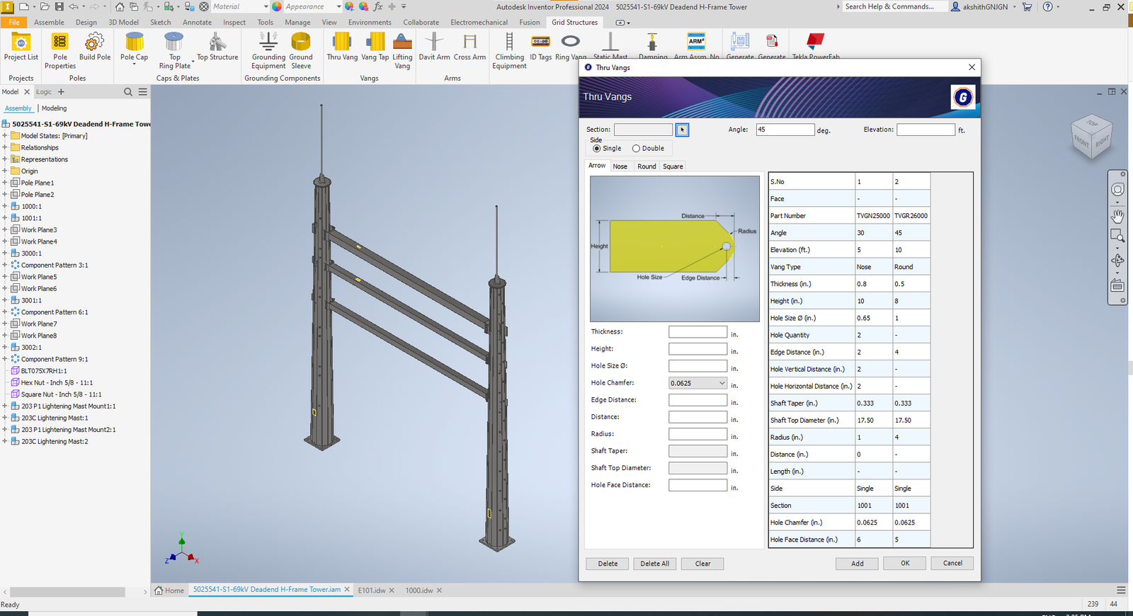
Input validation rules prevent impossible or out-of-range combinations. For batch processing, parameters can be imported from structured Excel or CSV files, allowing dozens of pole designs to be queued for sequential generation.
Automated Step 2: 3D Model Generation
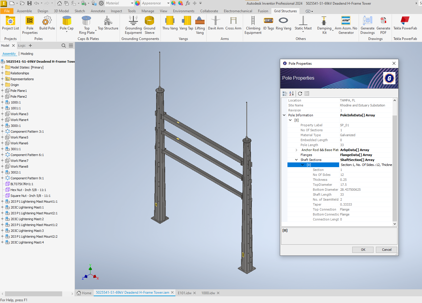
Once parameters are confirmed, the system generates the complete 3D model automatically. The Inventor API and iLogic rules drive parametric model generation:
- Pole shaft is generated with correct taper, wall thickness, and cross-section (round, 12-sided, 16-sided, or other polygonal shapes)
- Base plate is generated with correct dimensions, bolt hole patterns, and weld preparations
- End connections (plates or vangs) are generated with full parametric accuracy
- Arms are placed at correct orientations and heights with proper connection geometry
- Vangs are generated per the selected type and orientation parameters
- Hardware (bolts, nuts, washers) is automatically selected from the library and placed in the assembly
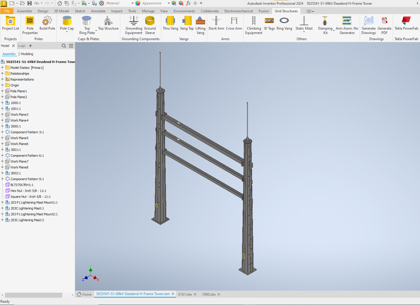
The 3D model is a fully constrained assembly with proper part relationships. Changing any parameter regenerates the entire model consistently. Generation time: typically under 5 minutes for a complete pole assembly, versus 8-12 hours manually.
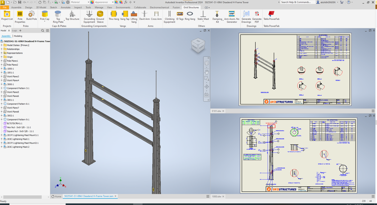
Automated Step 3: 2D Drawing Generation
From the 3D model, the system automatically generates fabrication-ready 2D drawings:
- Standard views are placed per your company's drawing layout template
- All dimensions are applied automatically following your annotation standards
- Weld symbols, surface finish callouts, and fabrication notes are placed by rule
- The title block is populated with project data, part numbers, material specifications, and weights
- Section views and detail views are generated where needed
- Balloon callouts are placed and linked to the BOM
The output formats match your CAD platform: IDW and DWG for Inventor, DWG for AutoCAD, SLDDRW and DWG for SolidWorks, plus PDF across all platforms.
Automated Step 4: BOM and Part Number Generation
The BOM is generated directly from the 3D model data. Every component in the assembly is automatically cataloged with:
- Part number following your company's numbering convention
- Quantity, description, material grade, unit weight and total weight
- Hardware pallet parts list: All bolts, nuts, washers, and loose hardware
- Ship loose items list: Items shipped separately from the main assembly
Because the BOM is extracted directly from the 3D model, there is no possibility of a mismatch between what the drawing shows and what the BOM lists. This single-source-of-truth approach eliminates an entire category of manufacturing errors.
Automated Step 5: Review and Release
The engineer reviews the generated outputs. Because the system is rule-driven and validated, the review step becomes a quality confirmation rather than an error-hunting exercise. If changes are needed, the engineer modifies the input parameters and regenerates. All outputs update simultaneously.
What Changes for Your Engineering Team
The shift from manual to automated design changes the engineering team's role:
| Before Automation | After Automation |
|---|---|
| Engineers spend 60%+ of time on repetitive modelling and drafting | Engineers spend 80%+ of time on structural analysis and project engineering |
| Senior drafters consumed by routine pole drawings | Senior drafters handle only non-standard or custom work |
| Throughput limited by available drafting hours | Throughput scales with project volume |
| Errors discovered during fabrication cause rework | Errors prevented at generation through validation rules |
| BOM accuracy depends on manual diligence | BOM accuracy is structural (extracted from model data) |
Implementation: What It Takes
This automation is not a downloadable product. It is a custom engineering service. Each implementation is built around the specific requirements of the manufacturer:
Discovery and audit (free). FDES Technologies analyzes your current PLS-Pole to fabrication workflow, identifies what is automatable, and provides a detailed assessment with expected results. Request a free automation audit.
Solution design. The automation architecture is designed around your pole types, drawing templates, part numbering conventions, hardware libraries, and downstream system requirements.
Development and iteration. The custom CAD add-in is built iteratively with your engineering team's feedback. You see working automation early in the process, not just at the end.
Testing against your real designs. The system is validated against your actual pole designs to verify 3D model accuracy, drawing completeness, BOM correctness, and fabrication data integrity.
Deployment and training. Your team operates the automation independently after training. Ongoing support is available as needed.
Typical implementation timeline: 8-16 weeks depending on scope and complexity.
FDES Technologies has 16 years of experience in design automation and CAD customization, with deep expertise across Autodesk Inventor, AutoCAD, SolidWorks, and other CAD platforms. This automation is currently deployed with US-based tubular steel transmission pole manufacturers.
Measuring the Impact
The metrics from existing deployments:
- Design time reduction: 80-90% (days per pole to minutes per pole)
- Drawing error rate: Near zero (rule-based validation prevents errors at generation)
- BOM accuracy: 99.9% (automated extraction from 3D model)
- Engineering capacity freed: 60% of engineering time redirected from drafting to higher-value work
To estimate the specific ROI for your operation, use the FDES ROI Calculator or request a free automation audit.
Start with a Free Automation Audit
If you want to see how automation applies to your actual pole designs, FDES Technologies offers a free automation audit. We analyze your current PLS-Pole to fabrication workflow and identify the specific automation opportunities. No cost. No commitment. Your data remains confidential.
Related Resources: