The Problem: What Manual IS:807 Design Actually Looks Like
India has hundreds of MSME crane manufacturers: small and mid-size companies producing electric overhead travelling cranes for factories, warehouses, and industrial facilities across the country. The Indian overhead crane market is growing at over 10% annually, driven by manufacturing expansion and infrastructure investment. Yet the engineering workflow inside most of these companies looks the same as it did twenty years ago.
When an order comes in for a 10-tonne, 18-metre span EOT crane, an engineer sits down with IS:807:2006, IS:3177, and IS:800, works out the loading conditions, computes bending moments and shear forces, looks up allowable stresses based on the steel grade, selects a girder cross-section from a reference table, runs it through a series of code checks, and adjusts if anything fails. The same process repeats for the end carriage. Stiffeners are designed. A calculation report is compiled.
It takes two to four hours for an experienced engineer. For a manufacturer producing 100 cranes a year, that's 200–400 engineer-hours spent annually on structural calculations, before a single drawing is produced.
The hidden cost is significant. An engineer at INR 500/hour doing three designs per week is spending INR 75,000–150,000 per year on calculation work alone. The visible cost is slower: missed quotes, delayed approvals, and the constant risk of errors that only surface when the crane is being inspected on site.
Why Excel Templates Fail Crane Manufacturers
Most manufacturers who have tried to systematise this work have done it with Excel. A senior engineer builds a spreadsheet that encodes the IS:807 procedure, another engineer uses it for a few years, and at some point the original author leaves the company. Nobody is entirely sure which version is current. A formula is broken somewhere in column AQ. The section lookup table was last updated in 2019.
Excel calculation templates fail crane manufacturers in five specific ways:
- Version fragility: There is no version control, no audit trail, and no validation that the current file matches the code. Engineers modify templates for one project and forget to revert the changes.
- Knowledge concentration: The template only works correctly in the hands of the engineer who built it. Everyone else uses it as a black box and cannot verify the outputs.
- No optimisation: Excel templates check a single section the engineer selects manually. Finding the lightest valid section requires running the same spreadsheet twenty or thirty times for different cross-sections, something nobody actually does.
- Poor reporting: A formatted Excel printout is not a professional calculation report. Customers and inspectors have lower confidence in designs presented this way.
- No accessibility: Desktop files require the right version of Excel, the right computer, and are unavailable on the road or at a client site.
Desktop crane design software exists, but the available options are Windows-only tools with traditional perpetual licensing. They are expensive, require installation, don't run on-site, and are slow to update when code revisions happen. None of them are cloud-native, none use pay-per-use pricing, and none automatically find the lightest valid section.
What Automating IS:807 Design Actually Requires
When we started building Crane Genie, the first decision was the most important one: whether to simplify the calculation or automate it in full. The temptation in engineering software is always to approximate: skip the lateral torsional buckling check, use a simplified shear formula, hardcode a conservative safety factor and move on. We rejected this approach entirely.
A structural calculation tool that engineers trust must produce results that match what an experienced engineer following the code procedure would produce. Every shortcut is a source of distrust. If the tool selects a lighter section than an engineer's manual calculation, the engineer assumes the tool is wrong, even if the tool found a valid optimisation the engineer missed. The only way to build trust is to make the calculation engine fully transparent and fully correct.
This meant implementing the complete IS:807 load computation procedure:
- Full wheel load breakdown (R1–R8) with impact factors based on duty class
- Bending moment and shear force diagrams using the Barré method to position the trolley at the worst-case location along the span
- Dead load self-weight including vertical stiffener contribution, not a simplified area × density approximation
- Duty factor and dynamic inertia factor application per IS:3177
- Side force and torsional moment computation for rail-on-web configurations using the Bredt-Batho method
The calculation engine contains no simplifications. Every load case and every code check is implemented exactly as the standard requires.
The 13 Structural Checks That Cannot Be Skipped
IS:807 mandates a comprehensive set of structural checks for overhead crane girders. Engineers doing manual calculations sometimes skip the less obvious ones under time pressure. Automating the process means every check runs every time, with no exceptions.
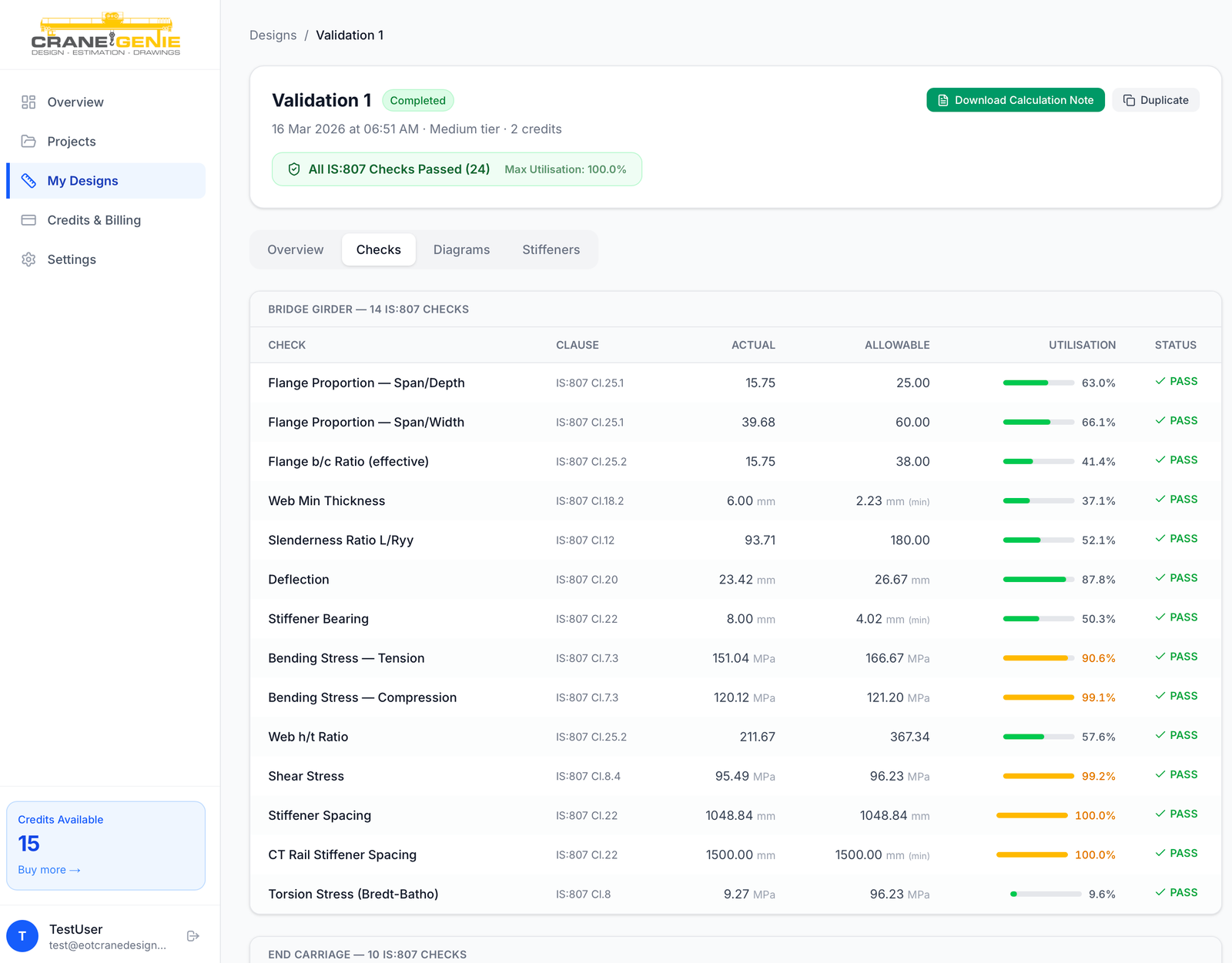
The engine runs 13 independent checks against every candidate girder section:
- Section proportions: span/depth ratio (≤25), span/width ratio (≤60), and flange b/c ratios to prevent slender or uneconomical geometries
- Web minimum thickness: based on the CT rail height and top plate thickness to ensure the web can sustain bearing loads under the rail
- Deflection: actual deflection vs. the IS:807 allowable of L/900 or L/1000 depending on duty class
- Bending stress (tension): maximum tensile bending stress vs. allowable based on yield strength and factor of safety
- Bending stress (compression): includes lateral torsional buckling reduction, which significantly limits allowable stress for long-span girders
- Web h/t ratio: prevents local web buckling between stiffeners
- Shear stress at neck section: uses the VQ/Ib formula at the weld junction, not the simplified V/A formula that overestimates capacity
- Von Mises equivalent stress: combined stress check per IS:807 Clause 16.2 using web shear, not neck shear
- Torsion (Bredt-Batho method): applies only to rail-on-web configurations; frequently omitted in manual calculations
- Stiffener bearing check: minimum plate thickness to prevent stiffener crushing under the concentrated bearing load
- Stiffener spacing (shear-based): maximum spacing to control web shear buckling per IS:807 Clause 22
- CT rail stiffener spacing: additional spacing constraint at the rail attachment zone
- Slenderness ratio: L/Ryy ≤ 180 to prevent column-like global instability of the entire girder
If any check fails, the section is rejected and the engine moves to the next candidate. The first section that passes all 13 checks is selected as the optimal design.
Finding the Lightest Valid Section: Why Iteration Beats Intuition
The most valuable capability in Crane Genie is one that sounds straightforward but is practically impossible to do manually: finding the lightest valid girder section for a given set of inputs.
An experienced crane design engineer, working manually, selects an initial section based on experience and rule-of-thumb (span/depth ratio, approximate bending moment), then checks it against the code. If it fails, they move up to a heavier section and check again. This process might involve three or four iterations before landing on a section that passes everything. But it rarely finds the absolute minimum weight section, because an engineer would need to start from the lightest possible section and work upwards, something that would take days if done by hand across a comprehensive section database.
The calculation engine iterates through a comprehensive library of pre-seeded girder cross-sections, sorted by cross-sectional area. For each section it runs all 13 structural checks. The first section to pass every check is selected. The result is always the mathematically lightest section that satisfies every IS:807 requirement, not the first adequate section an engineer happened to try.
In practice, this optimisation delivers girders that are 8–20% lighter than sections selected by experienced manual calculation. On a 10-tonne, 18-metre bridge girder fabricated from structural steel plate, that's a meaningful cost saving on every crane built.
Three design modes give engineers control over the optimisation target: Economical (minimum weight), Balanced (maximum utilisation ≤92%), and Conservative (maximum utilisation ≤85%) for applications where the engineer prefers additional margin.
End Carriage and Stiffener Design: The Parts Engineers Most Often Get Wrong
Girder design gets most of the attention in IS:807 calculations, but end carriage design and stiffener layout are where errors most commonly occur in manual calculation. The end carriage sizing problem is structurally similar to the girder problem (select the lightest section from a database of candidates that passes all relevant checks), but it's less well-documented and more frequently approximated.
The engine handles end carriage design by iterating through a full library of end carriage sections grouped by wheel diameter, running eight IS:807 checks against each, and selecting the optimal section. This runs automatically as part of every design calculation with no additional input required from the engineer.
Horizontal stiffener design, including calculating required moment of inertia, determining stiffener positions along the web height, and specifying ISA angle sections, is also fully automated. The engine computes stiffener requirements from first principles based on the selected girder geometry, rather than requiring the engineer to iterate through stiffener specifications manually.
Why the Report Matters as Much as the Calculation
A correct structural calculation that produces a poorly formatted output is not a finished design. In the Indian crane manufacturing context, the calculation report serves multiple audiences: the manufacturer's own engineering sign-off, the end customer's technical review, and the statutory inspector's acceptance check. Each audience expects different things from the same document.
Every Crane Genie design generates two report types automatically:
The PDF calculation report includes a professional cover page with design reference, full load computation with wheel load breakdown, bending moment and shear force diagrams (rendered from actual calculation data), cross-section geometry diagrams, stiffener layout, end carriage details, and all 13 check results with actual vs. allowable values, utilisation percentages, and IS:807 clause references on every line. Running headers and footers carry the design reference number through the entire document.
The DOCX structural calculation note provides the full hand-calculation trail in a format suitable for inclusion in project technical files, with every formula, every intermediate result, and every code clause cited explicitly.
The clause references are not cosmetic. Inspectors reviewing a calculation report that says "Shear stress τ = 487 kg/cm² ≤ τ_allow = 962 kg/cm² [IS:807:2006 Cl.16.3 PASS]" have a specific code reference they can look up and verify. This transparency is what converts a software-generated calculation into a document engineers and inspectors are willing to sign off.
The Right Business Model for MSME Engineering Software
Pricing model choices in B2B engineering software are often made by analogy to other software categories. Annual subscriptions work well for tools engineers use every day. Per-seat licensing works for team-wide platforms. Neither model fits well for MSME crane manufacturers whose design volume varies significantly month to month with order flow.
Crane Genie uses a credit-based pay-per-design model. New users receive three free trial credits on registration. Paid credit packs are purchased as needed and never expire. The cost per design ranges from INR 999 to INR 1,499 depending on the complexity tier of the inputs, less than half the cost of outsourcing the same calculation to a freelance engineer and a fraction of the time.
This aligns with how MSME manufacturers think about professional services costs. A business producing 40 cranes a year doesn't want to pay a monthly subscription during quiet months. A business producing 200 cranes a year benefits from the volume pricing of larger credit packs. Credits purchased during a busy quarter are available during a slow one.
What This Project Taught Us About Engineering Calculation Automation
Building Crane Genie surfaced several principles that apply beyond crane design to any engineering calculation automation project.
Accuracy is a prerequisite, not a differentiator. An automated tool that produces a different answer than the code procedure is not useful, regardless of how fast or well-presented it is. The calculation engine must be demonstrably correct before anything else matters. The 43 unit tests in the engine, each validating known crane configurations against expected output values, exist for this reason.
Transparency builds trust faster than any other design decision. Showing engineers every intermediate calculation, every code clause, every utilisation percentage is not just good practice. It's the only way a new tool earns trust from engineers who have spent years doing these calculations by hand. The moment an engineer can verify that the tool reached the same intermediate value they would have computed themselves, the trust barrier falls.
Optimisation is only possible through automation. No engineer manually iterates through hundreds of sections to find the lightest valid design. The optimisation capability, producing minimum-weight designs that pass all code checks, is something automation can deliver that humans genuinely cannot, and it has direct economic value in material cost savings on every crane built.
The broader lesson is one we apply across all engineering calculation automation work at FDES: the value of automation in engineering is not that it replaces engineering judgement. It handles the deterministic, rule-based execution of established procedures, freeing engineers to focus on the genuinely complex problems where judgement matters. An engineer who isn't spending three hours on a girder calculation has three hours to spend on an unusual loading condition, a non-standard configuration, or a customer specification that genuinely requires engineering thought.
That reallocation of effort, from mechanical procedure execution to actual engineering, is the real return on automation investment. For Indian crane manufacturers competing on speed, accuracy, and cost, it's not a nice-to-have. It's a competitive necessity.
If your team handles repetitive structural calculations, compliance checks, or design procedures that follow established rules, the same approach applies. Explore how we approach engineering calculation automation and variant drawing automation, or talk to us directly about what you're working on.